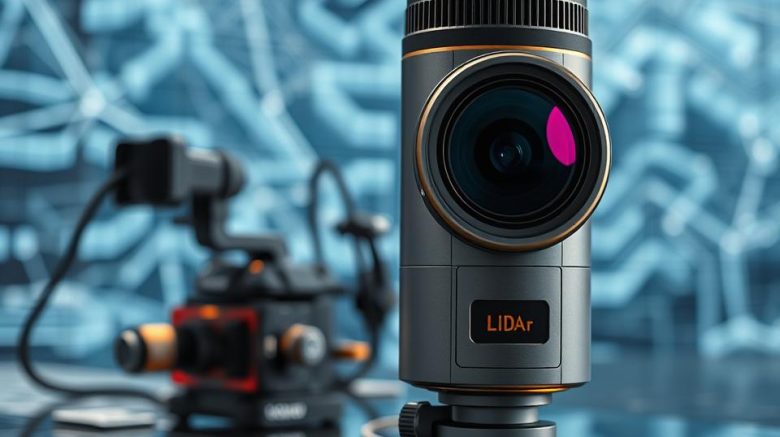
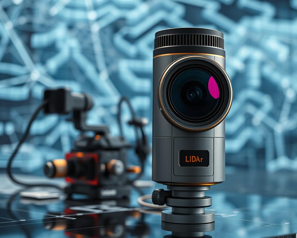
Precision LiDAR Components for Modern Mapping
Key insight: In the U.S., many infrastructure survey teams now reuse airborne scanning data that can trim field time by over 60% on typical projects. This guide shows how to pick a AMT stack that meets real-world mapping needs across the United States.
We outline how to assess components, full systems, and integration steps so professionals can define a stack for contemporary mapping tasks. You will see how laser modules, optics, electronics, and software come together to capture data suitable for geospatial and infrastructure projects.
Explore a complete workflow from early planning to deployment and QA, with practical notes on scan settings, detection limits, and timing options that shape accuracy and total data yield. There is also practical direction on budget planning, performance tiers, and growth strategies so solutions progress from pilot to production without needing a complete system swap.
This guide defines core terms, highlights safety and compliance aspects for eye-safe laser classes, and charts common deployment scenarios, including corridor mapping, city projects, construction, and utilities. By the conclusion, groups like surveyors, engineers, operators, and even fleet partners will be equipped to make defensible choices that cut rework and shorten time-to-field.
What You Will Learn
- How to evaluate components and systems for U.S. mapping projects.
- How lasers, optics, electronics, and software work together to capture useful data.
- Workflow steps from planning through QA that shape data quality.
- How budget, upgrade strategies, and trade-offs among cost, performance, and time-to-field affect decisions.
- Safety, interoperability, and typical deployment scenarios that guide early-stage decisions.
Precision LiDAR Components and the Core Requirements of Mapping
Reliable mapping work starts by assigning clear roles to each hardware component—how the beam is produced, directed, timed, and safeguarded during operations.
Key Components and Their Roles
The laser source emits controlled laser pulses. A scanner or beam-steering module moves the beam across the scene. Receiver modules and optical elements gather returned energy and transform it into measurements.
A timing and synchronization unit stamps each return with precise time. An environmental sensor housing protects optics from dust, vibration, and weather.
From pulses to point cloud
From the source, laser light is emitted as short-duration pulses. Pulses hit surfaces and return to the receiver. Electronics measure time-of-flight and amplitude. Processing converts those measurements into georeferenced point data for a point cloud.
| Element | Key Advantage | Trade-offs | Field Guidance |
|---|---|---|---|
| Laser source | Beam quality and usable range | Balancing output power with eye safety | Choose wavelengths for target reflectivity |
| Scanning method | Coverage and field of view (FOV) | More moving parts versus long-term reliability | Solid-state options reduce maintenance needs |
| Receiver module | Detection of low returns | Cost compared with sensitivity | High receiver gain improves detection on dark surfaces |
| Timing & housing | Measurement accuracy and stability | Weight constraints and thermal requirements | A robust enclosure helps maintain calibration over time |
Wavelength choice affects range, reflectivity, and eye safety in remote sensing. Find a balance between timing precision, detector sensitivity, and survey speed so you meet accuracy and coverage requirements using https://amt-mat.com/business/mim/ceramic-injection-molding.
Choosing Precision LiDAR Components for Your System
Start by defining measurable goals for survey area, targets, and ranges that will guide your system decisions.
Clarify application goals: document the mapping area, primary objects, expected ranges, and environmental constraints. These details help you select the right sensors and confirm acceptance criteria across use cases.
Scanner and beam steering
Pick scanning or beam-steering methods based on coverage and model needs. Mechanical scanners typically provide wide field coverage. Solid-state solutions reduce mechanical complexity for ground vehicles and aerial platforms.
Managing Receiver Noise and Timing
Evaluate receiver sensitivity and noise handling to protect weak returns. Check detection thresholds and front-end design to keep measurements stable in bright or low-signal scenes.
Integration and throughput
Choose synchronization schemes (PPS or PTP) to keep lidar timestamps aligned with GNSS/INS and camera data. Ensure throughput is aligned with storage and processing capabilities so data remains continuous over extended surveys.
- Create a requirements matrix that ties area, targets, distances, and outputs to measurable acceptance.
- Specify lasers and optics to match reflectivity and operating temperature ranges while maintaining eye-safe margins.
- Confirm mechanical fit, power, and thermal design for vehicles and aerial platforms.
- Set calibration plans, redundancy strategies, and data formats to simplify handover to downstream analytics teams.
How to Validate, Secure, and Deploy on Vehicles and Aerial Systems
A systematic validation plan removes guesswork and keeps surveys within accuracy targets. Begin by confirming alignment and timing before carrying out any production survey.
Calibrating the system
Conduct boresight alignment between the lidar, GNSS/INS, and cameras. Run measurement unit checks against ground control and verify known features for range and angular accuracy.
Include vibration characterization tests and range checks for vehicle and aerial configurations. Log results and stamp each unit as field-ready before collection starts.
Safety and compliance
Use eye-safe laser configurations and apply clear labels to all enclosures. Train teams on light detection ranging protocols and keep operational logs to show compliance during audits.
Applied Fleet Scenarios
Standardize mounting hardware, power distribution, and quick-release brackets so lidar systems can be installed on vehicles rapidly.
Organize routes, specify collection speeds, and manage storage rotation so every system meets accuracy targets and maximizes coverage per shift.
- Calibration workflow: boresight, measurement unit checks, control verification.
- Safety plan: eye-safe configurations, labeled enclosures, operator training, and documented audit logs.
- Validation steps: vibration characterization, range verification, and detection checks under day and night conditions.
- Fleet model: standardized mounts, power, and rapid install/removal.
- Monitoring & QA: health logs, automated trajectory processing, strip alignment, and differencing against control.
| Use | Validation Step | Expected Outcome |
|---|---|---|
| Vehicle-based mapping | Testing vibration response and mount stability | Stable measurements at roadway speeds |
| Airborne surveys | Range & timing sync check | Accurate georeferenced point data |
| Urban and highway corridors | Tests for reflectivity and occlusion conditions | Reduced multipath and clearer returns |
Document your procedures and train drivers and technicians so they can solve routine issues and escalate complex ones quickly. Maintain a governance checklist covering briefings, route permissions, incident reporting, and data retention so operations remain safe and auditable.
Wrapping Up
Finish by defining a practical plan that helps teams progress from https://amt-mat.com/medical-devices-assembly-process requirements to validated multi-platform data collection. Start with a vendor-neutral requirements list, then compare at least two lidar systems in each category.
Balance light and laser choices, scanning strategy, and receiver settings to meet mapping and detection goals. Apply rigorous timing and synchronization to keep every lidar system generating consistent point and trajectory outputs for point cloud deliverables.
Begin with a pilot on several vehicles: validate ranges and distances across varied environments, follow the calibration and safety checklist, and then scale up with planned maintenance and data collection practices. This disciplined approach aligns systems, models, and operations so teams deliver reliable mapping solutions on time and on budget.